CV Lecture 8
CV Lecture 8
What is stereoscopic vision
- Stereoscopic vision describes the ability of the visual brain to register a sense of three-dimensional shape and form from visual inputs.
- In current usage, stereoscopic vision often refers uniquely to the sense of depth derived from the two eyes.
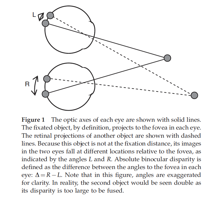
The fovea centralis (fovea) is a small depression at the centre of the retina. It provides the sharpest vision in the human eye, also called foveal vision. The central fovea contains a high concentration of retinal cells called cone photoreceptors. Cone cells help us see colours and fine details.
What is stereo vision?
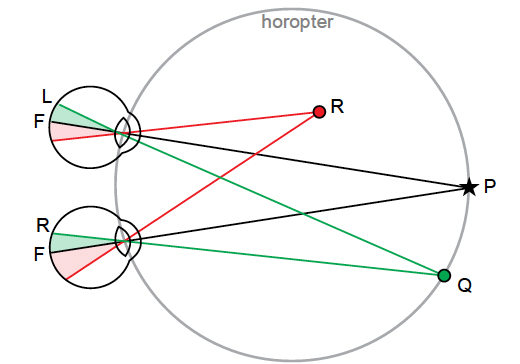
- The horopter was originally defined in geometric terms as the locus of points in space that make the same angle at each eye with the fixation point.
- In more recent studies on binocular vision, it is taken to be the locus of points in space that have the same disparity as fixation.
Why do we need stereo vision?
- The world is not flat, we live in a three dimensional world
- A camera captures the world and stores it as images
- Images are two dimensional
- What is the relation between the world and an image?
- Can we reconstruct the 3D world starting from more images?
- We can if we can establish a correspondence between different views of a scene
Perspective projection
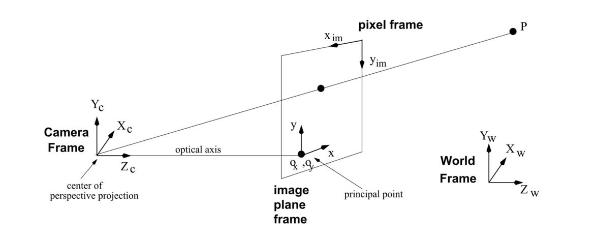
- The camera exists in a 3D Cartesian frame
- The image is a planar object
- It has its own coordinates
- The focal length $f$ defines the distance between the image plane and the center of projection $O$
- The line through $O$ and perpendicular to the image plane is the optical axis
- The intersection of the optical axis with the image plane is called principal point or image center
image->2D eyes->3D

- A point P in the world is projected onto a point p on the image
World and camera coordinate frames
A camera reference frame is usually rotated and translated with respect to the world reference frame. 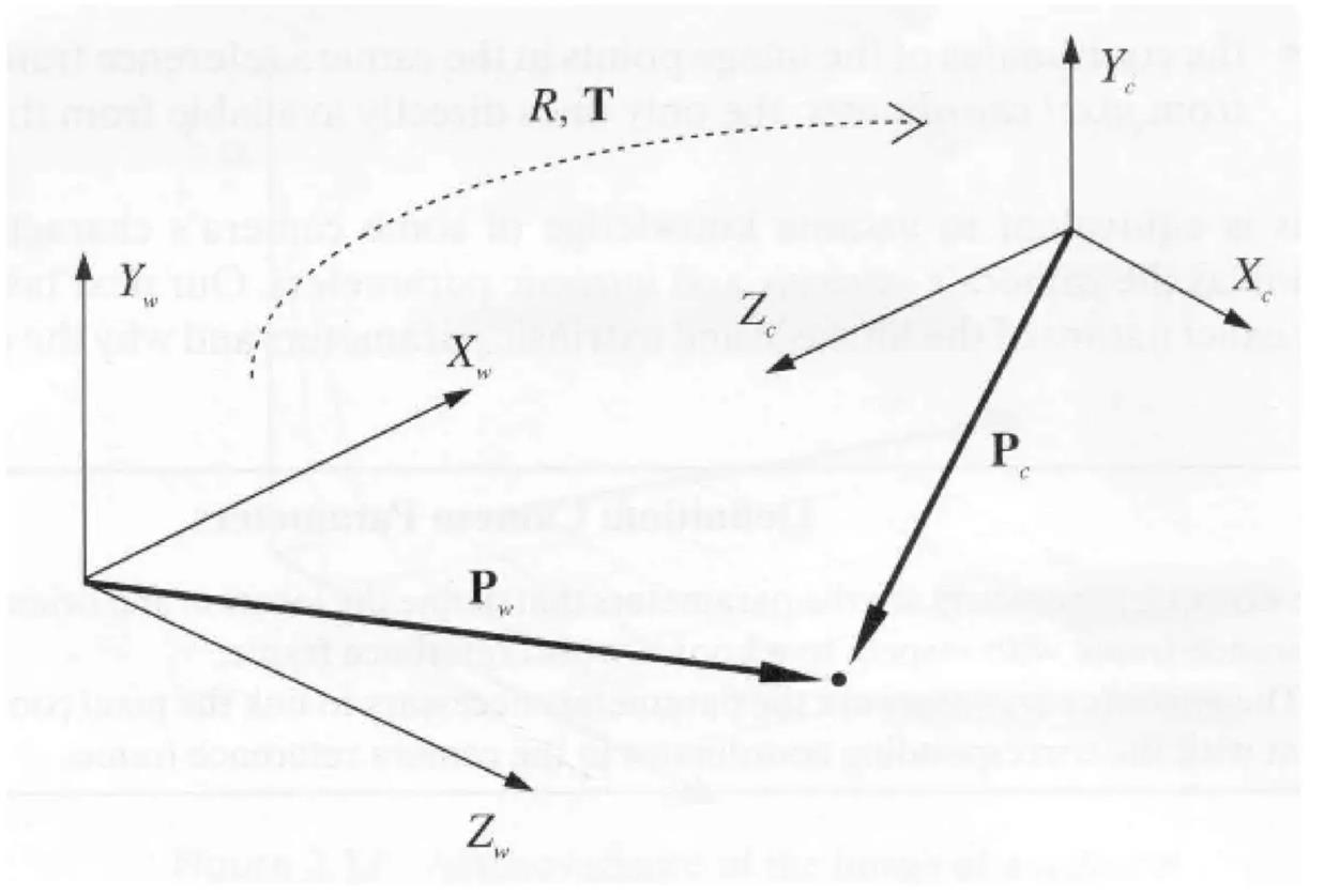
- A rotation matrix $R$ and a translation vector $t$ describe mathematically the transformation.
Summary of camera parameters
Extrinsic camera parameters
the parameters that define the location and orientation of the camera reference frame with respect to a known world reference frameIntrinsic camera parameters
the parameters necessary to link the pixel coordinates of an image point with the corresponding coordinates in the camera reference frame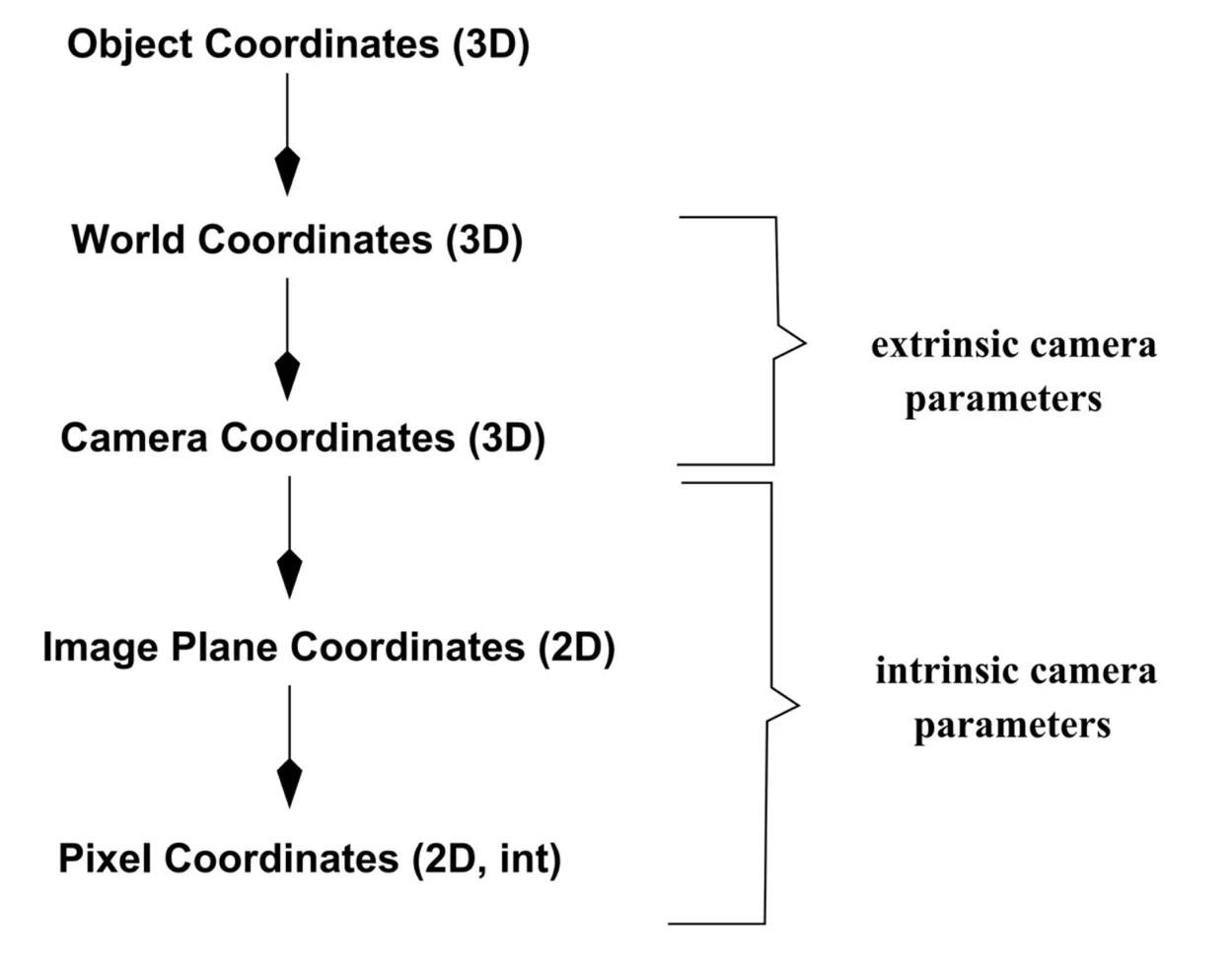
From world to camera coordinate frames
$$
P_c = R(P_w - T) \quad \text{where} \quad R = \begin{bmatrix} r_{11} & r_{12} & r_{13}
r_{21} & r_{22} & r_{23}
r_{31} & r_{32} & r_{33} \end{bmatrix}
X_c = R^T_1(P_w - T)
\[\]Y_c = R^T_2(P_w - T)
\[\]Z_c = R^T_3(P_w - T)
\[where $R^T_i$ corresponds to the i-th row of the rotation matrix # From camera to image coordinates\]x = f\frac{ X^c}{Z^c} = f \frac{R^T_1(P_w - T)}{R^T_3(P_w - T)},
\[\]y = f\frac{ Y^c}{Z^c} = f \frac{R^T_2(P_w - T)}{R^T_3(P_w - T)}
\[ # From image to pixel coordinates\]x = -(x_{im} - o_x)s_x \quad \text{or} \quad x_{im} = -\frac{x}{s_x} + o_x,
\[\]y = -(y_{im} - o_y)s_y \quad \text{or} \quad y_{im} = -\frac{y}{s_y} + o_y
\[Where $s_x$ and $s_y$ correspond to the effective size of the pixels in the horizontal and vertical directions (in millimeters) ## Properties - The projection of a point is not unique (any point in the world on the line OP has the same projection) - The distance to an object is inversely proportional to its image size 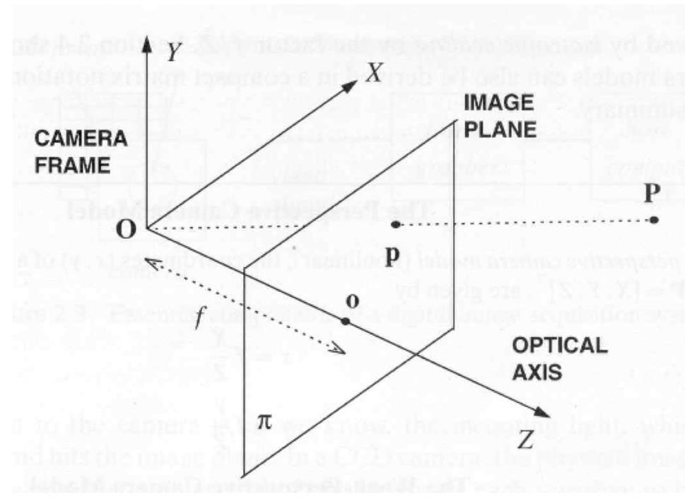 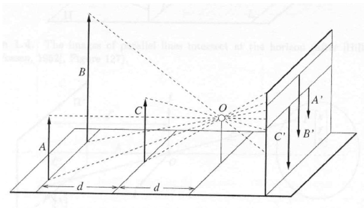 - When a line (or surface) is parallel to the image plane, the effect of perspective projection is scaling. - When a line (or surface) is not parallel to the image plane, we use the term foreshortening to describe the projective distortion. - (i.e., the dimension parallel to the optical axis is compressed relative to the frontal dimension) 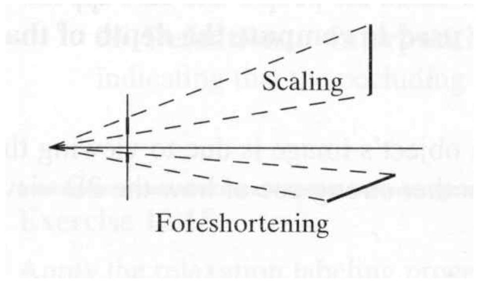 - Lines in 3D project to lines in 2D - Distances and angles are not preserved - Parallel lines do not in general project to parallel lines (unless they are parallel to the image plane)  # Effects of focal length As $f$ gets smaller, more points project onto the image plane (wide-angle camera) - **Left Image**: Wide-angle image of an electric guitar - **Right Image**: Wide-angle portrait of another pooch 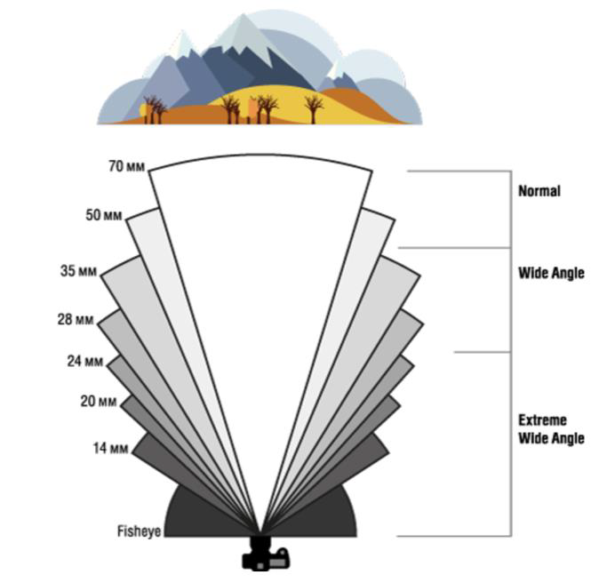 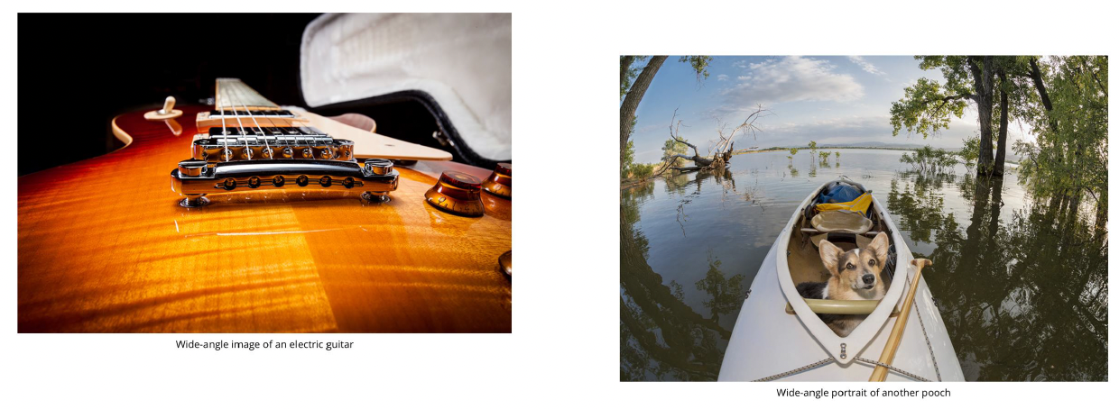 As $f$ gets larger, the field of view becomes smaller (more telescopic)  # More cameras  # Problem - When two cameras look at the same scene, and there is an overlapping between the views - Then, the shared information (overlapping region of space) can be used to find corresponding information - We can then measure the distance from both cameras - Combining such information gives us a 2D ½ view of the scene - It is called so because we cannot see behind the part of the image for which we have depth information - We do not have a proper 3D reconstruction # Binocular Stereo - We use the so called triangulation principle - We then - Extract features from the left and right image - Search for correspondence between the extracted features - Perform the triangulation 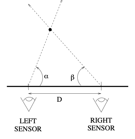 # Stereo algorithm - The input to stereo vision is a set of two or more images of the same scene taken at the same time from cameras in different positions. - The positions and orientations of the two cameras in the world are assumed to be known; if fixed on a rig, their relative pose can be calculated using a calibration target. - The output is a depth map. 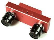 # Stereo - A point with coordinates $X$ in the rig reference system projects to point $x_1$ in image 1 and $x_2$ in image 2. - These two points are said to correspond to each other. - From the differences in the image positions of corresponding points, a computation called triangulation determines the coordinates $X$ of the point in the world, relative to the rig reference system. - Triangulation is straightforward geometry, while determining pairs of corresponding points is a hard task, the so-called correspondence problem. 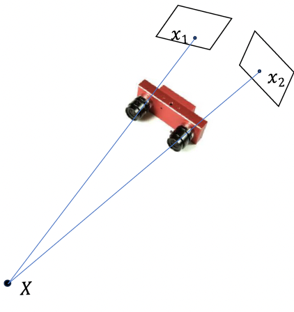 # What features can we use? - We have seen quite a few - We could use edge information - We could use interest points (SIFT etc.) - We could use image intensity patches 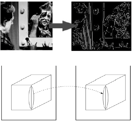 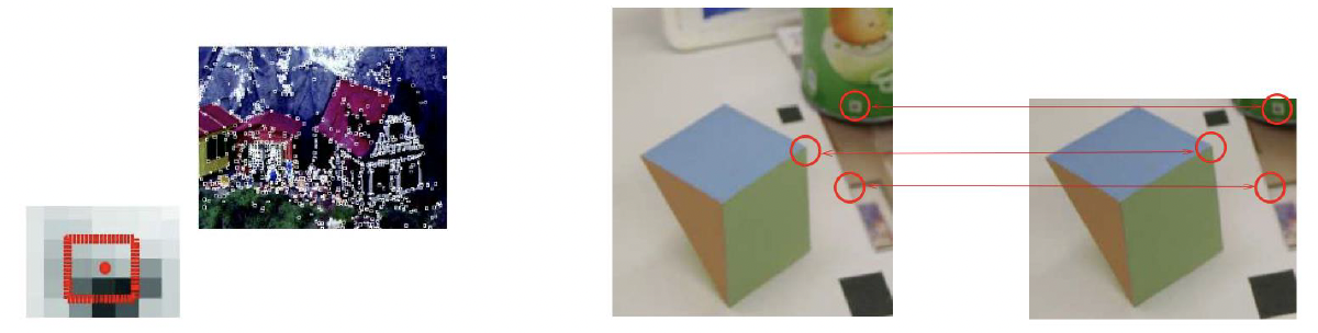 # Stereo Matching algorithm - We want to match features found in two overlapping views - We run our favourite feature detector in both images - We then find an algorithm that matches the two sets, to find correspondences - We can use RANSAC to distinguish between inliers and outliers - Read the next slides for more detail on it # RANdom SAmple Consensus (RANSAC) >M.A. Fischler and R.C. Bolles. Random sample consensus: A paradigm for model fitting with applications to image analysis and automated cartography. Communications of the ACM, 24(6):381–395, 1981. - It is a general parameter estimation approach designed to cope with a large proportion of outliers in the input data - RANSAC is a resampling technique that generates candidate solutions by using the minimum number observations (data points) required to estimate the underlying model parameters - Unlike greedy algorithms, RANSAC uses the smallest set possible and proceeds to enlarge this set with consistent data points # The Algorithm ## Algorithm 1 RANSAC 1. Select randomly the minimum number of points required to determine the model parameters. 2. Solve for the parameters of the model. 3. Determine how many points from the set of all points fit with a predefined tolerance ε. 4. If the fraction of the number of inliers over the total number of points in the set exceeds a predefined threshold τ, re-estimate the model parameters using all the identified inliers and terminate. 5. Otherwise, repeat steps 1 through 4 (maximum of N times). - The number of iterations, $N$, is chosen high - It is high enough to ensure that - the probability $p$ that at least one of the sets of random samples does not include an outlier # Using SIFT Let us say we used SIFT in both left and right images 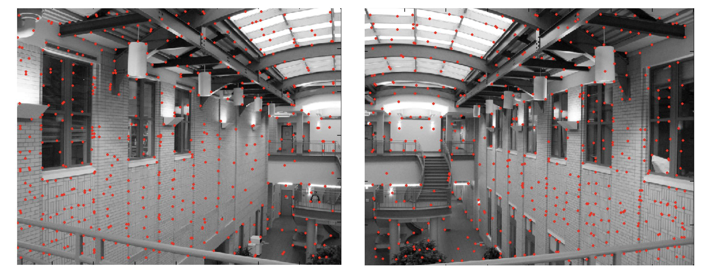 # Using RANSAC - **Red points:** points without a “good” match in the other image - Good means the ratio of the distances to the second nearest neighbour and first nearest neighbour - **Blue points:** “good” match in which the match was wrong - **Yellow points:** correct matches - RANSAC must run until it randomly picks 4 yellow points from among the blue and yellow points (the matches estimated to be “good”) 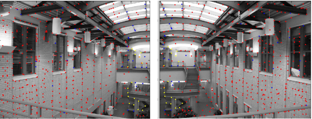 # Outlier rejection - We match only those features that have similar enough matches - This can be done exhaustively, searching for all the possible matches - A cleverer method is to assume the cameras are not too far apart and they look roughly at the same scene from similar perspectives - This means a feature from one camera must be close to a feature in a larger corresponding area in the second camera # Correspondence problem: template matching It is performed by choosing a template window from the first image and use a correlation technique to match it against a region of interest in the second image. 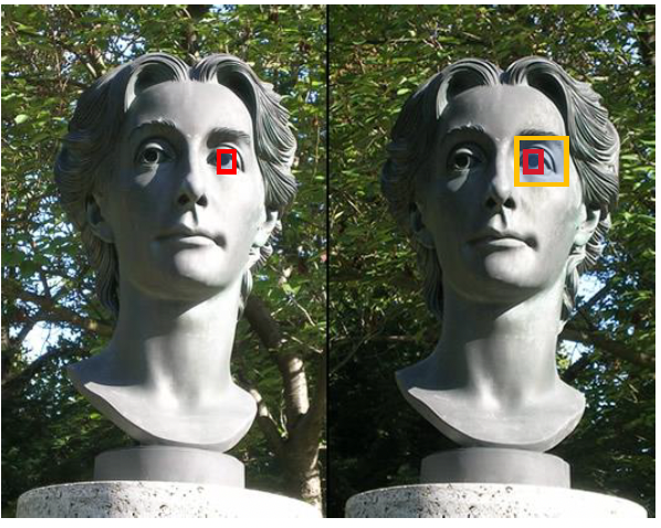 # Sum of Squared Differences (SSD) - It is a measure of match based on pixel by pixel intensity differences between images - It calculates the summation of squared for the product of pixels subtraction between two images\]| SSD(u, v) = \sum_n \sum_m | I(u + m, v + n) - T(m, n) | ^2. |
Ex = l’
$$ 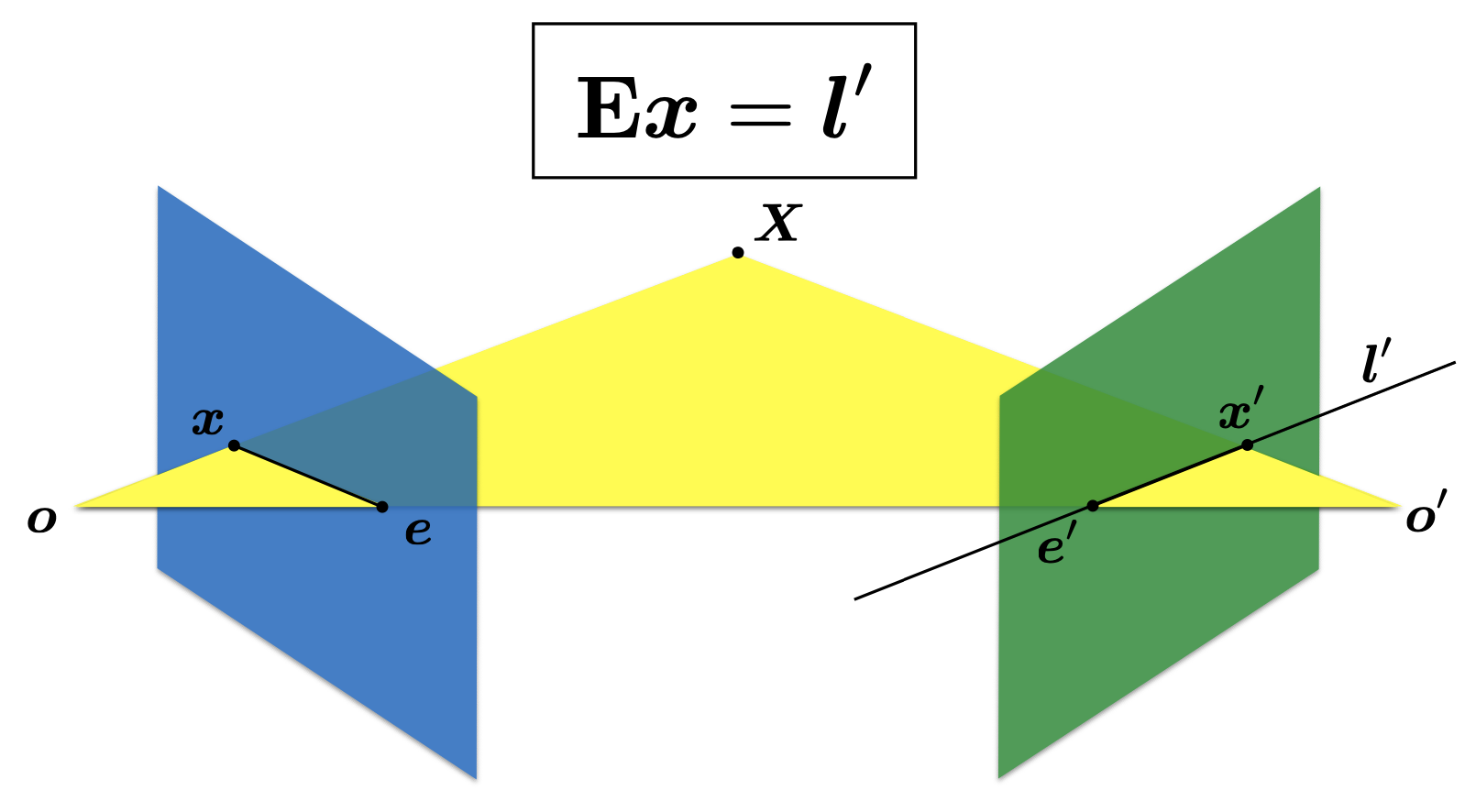 The essential matrix establishes constraints between matching image points
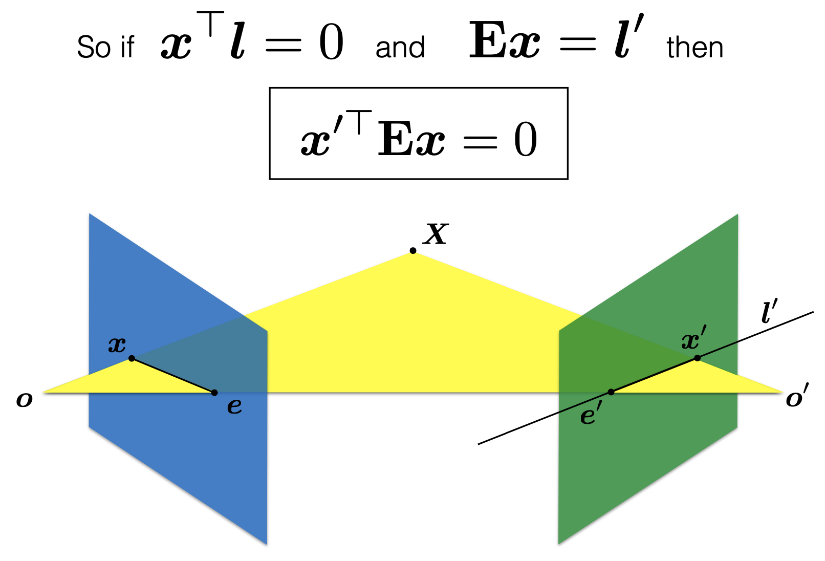
The Fundamental Matrix
- The Fundamental matrix is the equivalent of the Essential matrix when the cameras are calibrated.
- If $x_1$ and $x_2$ is a pair of corresponding points in two views, then they satisfy the scalar equation $x_2^T F x_1 = 0$.
- The fundamental matrix can be computed from correspondences of imaged scene points alone, without requiring knowledge of the camera internal parameters or relative pose.
Estimating camera poses in stereo pairs
- We can find the correspondences between the views
- We assume these are correct
- This is usually not the case, algorithms exist to rectify the problem
- Using the estimated correspondences and the epipolar constraint
- We estimate the Essential matrix E
- We then retrieve the relative pose (R, t), using E
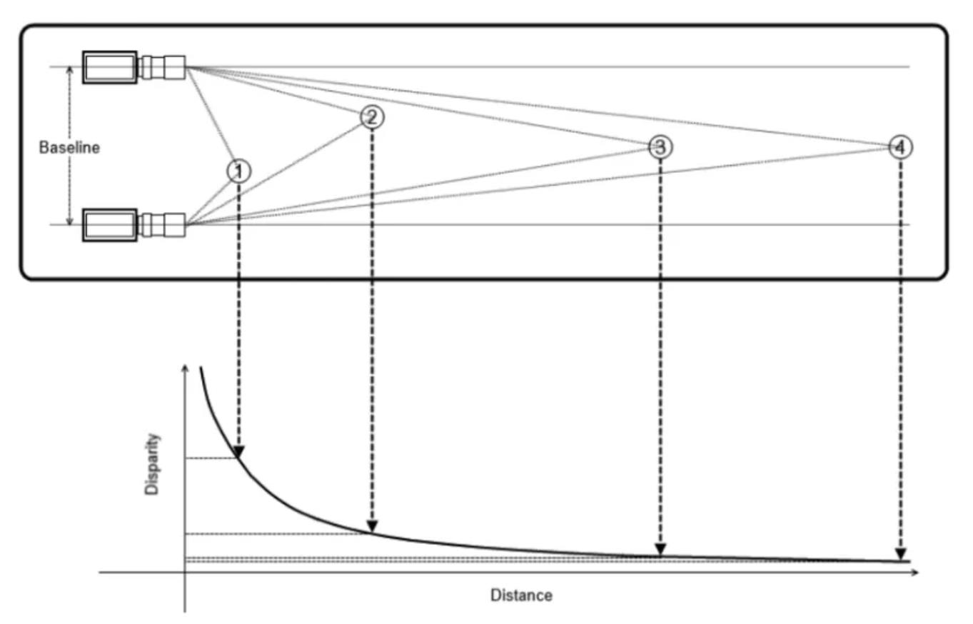
Baseline, Disparity, and Depth
- Depth is inversely proportional to disparity
- shift to the left of an image feature when viewed in the right image
- The larger the disparity, the closer the object is to the baseline of the camera
- The smaller the disparity, the farther the object is to the baseline.
Stereo Vision: sparse versus dense
- Sparse matching
- This is performed as we have discussed: we extract interest points for both camera views and then match
- It is called sparse because it has holes: not all points of the scene can be reconstructed as 3D
- Dense matching
- This is performed for all pixels
- We can interpolate across estimated sparse depths in the sparse matching
- We use correlation-based stereo
- use pixel neighbourhood as features
- compare using pixel correlation
- obtain depth at every pixel location in image
Stereoscopic sensors
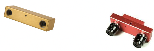
Use of Stereo Technology
Ubiquitous stereo vision device
Decision of camera layout by simulation
Camera arrangement is determined using the CAD data made beforehand. 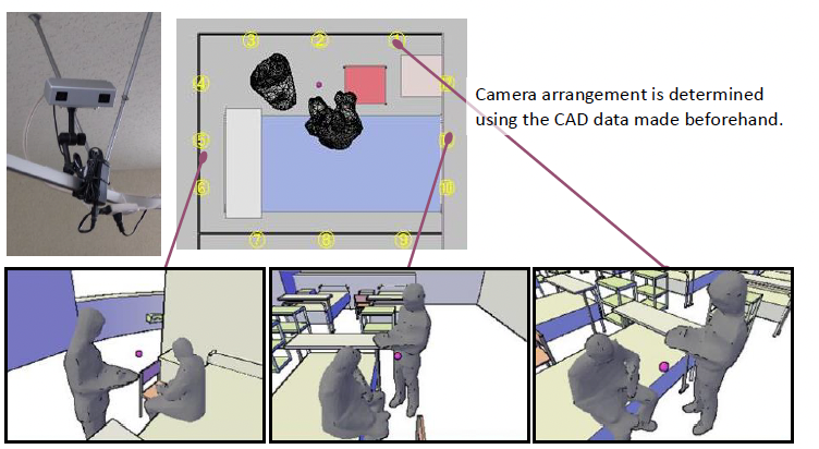
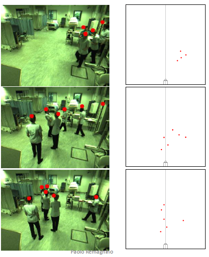
Head tracking in classroom
- Motion may be able to be evaluated from the position of the head, waist, or foot.
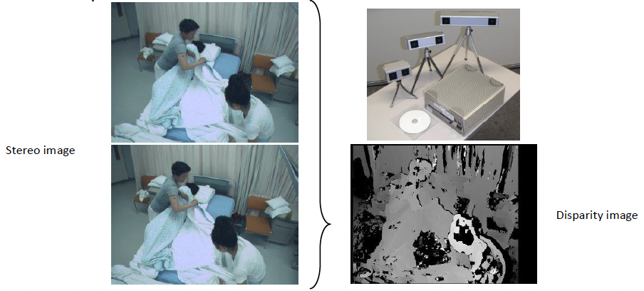
 …lots of examples
Summary
- We have taken a more detailed view of camera geometry
- Extrinsic and intrinsic camera parameters
- We have learnt about the geometry of a stereo pair of cameras
- We have seen how to transform a 3D world point onto an image point
- We have learnt about correlation methods
- We have seen the RGBD sensor and some applications