2025-09-15-Embedded Real-Time Systems 2
Embedded Real-Time Systems 2
Essentials of processor architecture
Agenda
- Motivation
- Von Neuman Architecture and its elements
- CPU elements and instruction processing
- Inputs and Outputs management
Essential Questions
- What is and why should we understand the underlying HW?
- How does a CPU work in principle?
- How do we get a CPU to interact with external world?
Objective
- Understand the basic concepts behind the processor architecture
- Get a sense of how the information gets processed at the CPU level
Why should we bother with getting this specific?
Hardware – Software Cohabitation
- In real-time systems it is essential to properly manage timing and latency requirements, and this is usually done through software
- In embedded systems integration of software and hardware is a requirement
- In embedded real-time systems software and hardware need to operate in unison to meet the complex system requirements
Variety of platforms
| Preferred by: | More suited for: | |
|---|---|---|
 | Application developers | Power |
 | System developers | Punctuality |
- Latest processor architectures, memory hierarchies, distributed system configurations, and ultra low power constraints make it more difficult to design truly punctual systems and the statistical response time distributions become significantly wider
- Real-time operating systems are major sources of uncertainty
- The increasing uncertainty in response times may degrade the robustness and performance in time-critical control systems with high sampling rates
No need to always go full DIY when designing, but know what your application requirements are and choose the platforms accordingly with these in mind
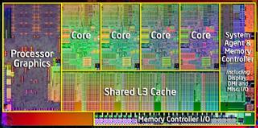
Basic processor architecture
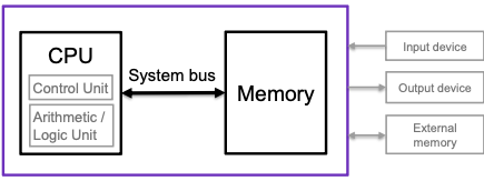
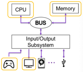
Von Neumann Architecture
Computer contains three elements:
- Central Processing Unit (CPU)
- System bus
Memory
- EDVAC was a binary serial computer (1944 by John Mauchly and J. Presper Eckert)
- Later built ENIAC, the first electronic general-purpose computer
- Automatic addition, subtraction, multiplication, programmed division, and automatic checking
- An ultrasonic serial memory capacity of 1000 34-bit words
- Average addition time was 864 μs
- Average multiplication time was 2900 μs
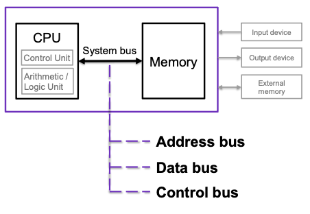
System Bus
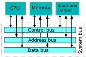
A set of three individual buses
- Address bus
- Unidirectional and controlled by the CPU
- The width of address bus is usually between 16, 32, 64 bits
- Data bus
- Bidirectional - transfers instructions and data
- Formed out of 4, 8, 16, 24, 32, 64, … data lines
- Control bus
- A mixed collection of control (e.g. read, write), status, clock, and power lines
Input/Output and Data Bus Protocols
- Input/output (I/O) registers are memory mapped (von Neumann architecture)
- Accessed in the same way as regular memory locations
- The data bus protocol can be either synchronous or asynchronous
- Synchronous: simpler implementation structure
- Asynchronous: more flexible with respect to different access times of memory and I/O devices (handshaking)
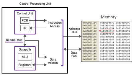
Central Processing Unit
Central Processing Unit (CPU) is the core unit where instruction processing takes place:
- Control unit
- Datapath
- Internal bus
*Integer data can usually be stored in 1, 2, 4, or 8 bytes
1 byte = 8 bits, 1 word = 2 bytes
Floating-point quantities typically occupy 4 or more bytes
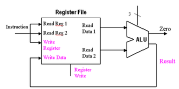
CPU - datapath
Datapath is a place in CPU where the data is being manipulated
The datapath contains
- Arithmetic-logic unit (ALU)
- Status registers
- Work registers
The datapath contains
- Arithmetic-logic unit (ALU)
- Status registers
- Work registers
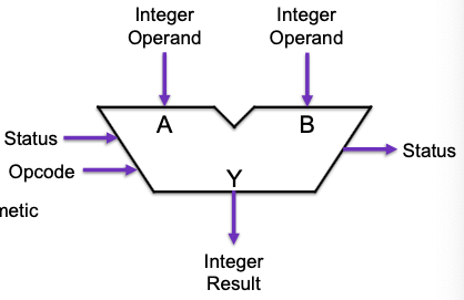
ALU is a combinational digital circuit that does arithmetic and bitwise operations on integer binary numbers 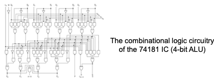
The datapath contains
- Arithmetic-logic unit (ALU)
- Status register
Work registers
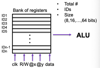
- Processor register is a quickly accessible location available to a computer’s processor
- Register file is an array of processor registers in a CPU which can be lumped into bank of registers
- Status register is a hardware register that contains information about the state of the processor (e.g. flag register)
- Work registers are pretty much all other registers (data, address, …)
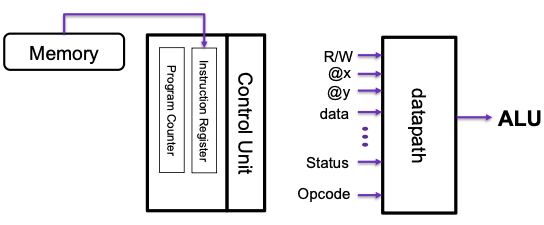
CPU – Control Unit
Control Unit (CU) is a component of a CPU that directs the operation of the processor
- Most computer resources are managed by the CU as it directs the flow of data between the CPU and all other devices
Why is 0x00400000 the default base address for an executable on a PC?
CPU – Internal bus
Internal bus is a bus that operates only within the internal circuitry of the CPU
- It is communicating among the internal caches of memory that are part of the CPU chip’s design
- This bus is very quick and is independent of the rest of the computer’s operations
Instruction Processing
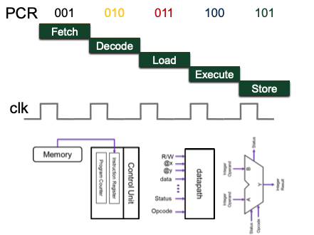
Instruction Processing
Instruction cycle consists of several consecutive instruction processing phases
Each phase takes a varying number of clock cycles to complete
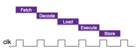
Here, we will consider a five-phase instructions cycle:
- Fetch instruction
- Decode instruction
- Load operand
- Execute ALU function
- Store result
- The duration of an instruction cycle depends on its function
- Not all instructions need Load, Execute, and/or Store phases
- Missing phases are either skipped or filled with idle clock cycles
- Every instruction is represented by its unique binary code
- E.g. 10000110 (0x86)
- A stream of such codes forms a machine-language program
- Mnemonic instruction codes are better known as assembly language instructions
- Examples: ADD, INC, NOP, SUB
- CPU uses binary codes only (ADD could be 10000110)
Assembly Instructions
When dealing with assembly-language programming, we need to know:
- The specific instruction set
- The available addressing modes
- The available register structure
op-code is assembly-language instruction code followed by operands
A generic instruction has the format:
op-code operand_1,operand_2
The length (bytes) of an entire instruction depends on the number and type of operands
Instructions may have one, two, three, or no operands
Assembly Instructions – addressing modes
The assembly language instructions here are typical yet vary from one processor to another
INC R1
(register direct)
- Increment the content of work register
R1
ADD R1,R2 (register direct)
- Add the contents of
R1andR2, and store the sum toR1
SUB R1,R2 (register direct)
- Subtract the content of
R1fromR2, and store the result toR1
NOP
(no operands)
- No operation, just increment the program counter register
ADD R1,R2 (register indirect)
- Add the content of
R1to the content of a memory location that is pointed by the address inR2, and store the sum toR1
INC &memory (direct)
- Increment the content of memory location
memory
ADD R1,5 (immediate)
- Add the content of
R1to number5, and store the sum toR1
Every instruction with a different addressing mode can be considered as an individual instruction
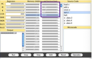
Instruction Processing
Fetch:
Get new instruction into Instruction Register, based on Program Counter value
Decode:
Translate what the instruction means
Load:
Move data from memory to data path register
Execute:
Move data through ALU
Store:
Write data from register to memory
Instruction Processing – Implementation
Microprogramming
- Every instruction is defined by a sequence of commands
- microinstructions, or micro-operation
- for activating datapath functions and required suboperations
- tend to use several clock cycles
- It is straightforward to construct machine-language instructions
Hard-wired logic
- Consists of combinatorial and sequential digital circuits
- Takes more space compared to microprogramming,
- Offers faster execution
- More difficult to create machine-language instructions when a hard-wired control unit is used
- Used in processors with either a small instruction set or a demand for very fast instruction processing
Both microprogramming and hard-wired logic are used in modern processors
Instruction Processing: ALU resources
The presented instruction-processing principle consists of sequential phases
- Assuming consecutive instructions have both internal and mutual dependency
- Prevents instruction-level parallelism
- Utilization of ALU resources is poor
Straightforward ways to increase computing performance without architecture change:
- High clock rate
- Wide buses
A large bank of work registers
- Direct connection to cost and hardware constraints
- Might be worth off for real-time systems as it delivers better response times and punctuality
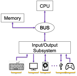
Inputs and Outputs (I/O)
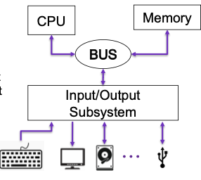
I/O in general
- Input and output ports to bring in excitations and to feed out corresponding responses
In real-time systems I/O actions are often strictly time constrained
- Keyboard: Input
- Sensor: Input
- Display: Output
- Disc: Input/Output
- USB: Input/Output
I/O: Von Neumann and alternatives
Input/Output subsystem has to
- Accommodate for the growth
- Handle ordering of the operations
- Account for plurality
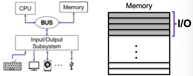
From the CPU perspective we can have:
Memory-mapped I/O:
- The input and output registers are in the regular memory space
- Inside memory block – use already available CPU instructions (load/read)
- Registers correspond to mode, status, configurable I/O ports
Programmed I/O:
- Requires an enhanced system-bus architecture
- Offers separate address space for I/O
- Has dedicated control signals (instructions) for input and output
1
2
IN R1, & port;        Read the content of port and store it to R1
OUT & port, R1;       Write the content of R1 to port
Which option is better for lower end microcontrollers that are to be used for real-time application and why?
I/O high-level overview
- Controller picks up the user intention
- CPU registers that the input is provided
- It reads it, compares the input to the rest of instructions stored in the memory as to interpret it
- CPU assigns appropriate output operation
- CPU outputs the graphical function
- Screen shows the graphical change
Polling
I/O CPU polling
How does CPU know that there is something coming in from I/O?
- Polling is constantly testing a port to see if data is available
- CPU polls (asks) the port if it has data available or if it is capable of accepting data
This might be very simple to implement, but it is extremely resource heavy…
Interrupts!
Interrupts
Interrupts
- An interrupt is an external hardware signal that initiates an event
- Interrupts are used to signal that an I/O transfer was completed or needs to be initiated
- While I/O ports can be crucial for any computer system, interrupts are essential in any hard real-time system
Why do we refer to it as interrupt?
Because the CPU goes about its business until it gets interrupted by a (hardware) flag, when it stops all (most) that it is doing and handles the interruption
The interrupt principle works fine as long as there is not too many of them simultaneously and the corresponding processing times are very short.
There are two main ways of classifying interrupt events:
- Maskable – events that occur during regular operating conditions (can be disabled, but one should be careful about this)
Nonmaskable – events that require immediate action
- External – coming from the I/Os or software
- Internal – (traps) which are handy in catching and handling exceptions (overflow, divide-by-zero, …)
Interrupt service process (in general)
Interrupts are usually a very prompt service, however, there are always a few latency elements that might take a moment.
So, an interrupt request is latched by the CPU, what happens next?
The interrupt request is latched by the CPU hardware
– it may take a moment to complete the ongoing instructionThe processing of the ongoing instruction is completed
– can also take some timeThe content of program counter register (PCR) is pushed to stack
The content of status register (SR) is pushed to stack
– this might need to be done by the interrupt process depending on the CPU architecture
Continued… We are just done with the housekeeping
- The PCR is loaded with the interrupt handler’s address from the Interrupt Vector Table
- a table that specifies the addresses of all the interrupt handlers
- The interrupt handler is executed
- can take some time depending on the type of interruption
- might need to handle the interrupt flag at this point and might need to announce that you are coming back from an interrupt
The original content of status register (SR) is popped from stack
- The original content of PCR is popped from stack
We didn’t get extra CPU time,
we just used what we have in a smarter way
Take Home Messages
- Understanding of the underlying hardware is essential for holistic ERTS design
- Von Neumann architecture focuses on CPU-memory relationship, but it is still very much applicable nowadays
- CPU comprises of a datapath, control unit, and an internal bus, all which play a crucial role in workings out of a digital (embedded) system
- Instruction processing takes place in 5 main phases: fetch, decode, lode, execute, and store – knowing them helps in handling the basic level functions
- I/Os depend on a dedicated subsystem whose working elements are architecture specific and are essential for interfacing with the CPU and Memory
- Polling and interrupt are two ways in which CPU can be made aware of I/O’s activity
- Interrupt is a more complex, yet much more efficient way of handling I/O’s and the understanding of it is crucial for successful ERTS design
Readings and Acknowledgement
P. A. Laplante and S. J. Ovaska, Real-Time Systems Design and Analysis: Tools for the Practitioner, 4th Edition. Hoboken, NJ: Wiley, 2012, page 27-36.
The lecture slides are in part adapted from the lecture slides of Prof. Seppo Ovaska and of Prof. Quan Zhou
Optional extra literature:
Essentials of Computer Organization and Architecture, 5th Edition. 5th edition. Jones & Bartlett Learning, 2018.
Assignment 1 is due today @23:59 2nd Assignment due 22/09 @23:59